ATMP facility for Mini/Micro-LED CoB/CoG display panels
A next-generation display platform offering industry-leading brightness, contrast, and operational lifetime, tailored for high-end applications such as mission-critical command and control centers, immersive video walls, digital information systems, corporate collaboration spaces, DCI-P3 cinema displays, automotive head-up displays (HUDs), and large-format commercial installations.
Crystal Matrix Panel (CMP) is a fine-pitch direct-view LED display platform engineered for the broadcast, enterprise, and premium AV markets. The CMP Series bridges the gap between commodity LED panels and ultra-premium proprietary systems, delivering broadcast-grade image quality at mid-to-premium pricing — through three engineering pillars:
Extended Bit Depth
16-19-bit native greyscale via MBI5292 / TBS5367A driver ICs — versus the 13-14-bit industry standard. 22-bit effective depth through hybrid PAM+PWM modulation.
HDR10 / HDR10+
Full SMPTE ST 2094-40 dynamic metadata processing — scene-adaptive tone mapping. Positions CMP alongside Samsung's The Wall as one of only two dvLED platforms with HDR10+.
Modular PCB Architecture
300 x 168.75 mm modules tiling into 600 x 337.5 mm (16:9) cabinets. Integer-multiple scaling from 108" Full HD to 135" 4K UHD through cabinet arrays.
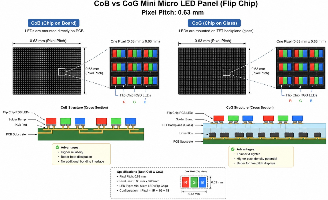
CoB & CoG Technology Architecture
CoB — Chip-on-Board (Flip-Chip)
CoB directly bonds bare flip-chip RGB LED dies onto the PCB substrate, then flood-encapsulates the entire module with black epoxy resin (4H Mohs hardness, ≥5B adhesion). The surface is a continuous matte resin free of wire bonds, with heat dissipating directly through the PCB copper planes and thermal vias. CoB is the dominant fine-pitch architecture, representing 57% of new panels in 2024-2025.
CoG — Chip-on-Glass (Active-Matrix)
CoG mass-transfers bare Micro-LEDs onto a glass substrate with TFT-style active-matrix row/column driving, bonded via anisotropic conductive film (ACF). The active-matrix backplane provides near-100% duty cycle, eliminating scan-ratio brightness loss. Results: module depth under 3 mm, OLED-class contrast >1,000,000:1, and refresh rates up to 12,000 Hz via AM driver ICs.
CoB & CoG Technology Architecture
Platform designation: CMP-FP (Fine-Pitch Modular) — targets professional AV and broadcast installations; CMP-AIO (All-in-One) — targets fast-deploy conference and boardroom applications.
Finest pitch: P0.625 mm (using 0102-class Micro LED dies, 25.4x50.8 µm). At this pitch, a 108-inch all-in-one display delivers native 4,800x2,700 pixels.
Manufacturing Process Flow
GaN Epi-Wafer Inspection
Incoming QC of 6” GaN-on-sapphire wafers (external or in-house). Includes electroluminescence (EL) mapping, wavelength binning, and forward voltage screening to ensure material quality and consistency.
Laser Singulation & Binning
Laser dicing of RGB wafers into individual chips. Chips are sorted based on wavelength, forward voltage, and brightness to create uniform and matched RGB sub-pixels for display applications.
Mass Transfer & Die Bonding
High-speed transfer of micro-LED chips onto PCB (Chip-on-Board) or glass (Chip-on-Glass) substrates. Precision flip-chip bonding is performed with micron-level placement accuracy to ensure alignment and reliability.
Driver IC & Assembly
Surface-mount placement of driver ICs and integration of power, control, and data interfaces. Supports connectivity via HUB, Gigabit Ethernet, or optical communication systems.
Black Resin Encapsulation
Application of black epoxy encapsulation layer for environmental protection, improved contrast, and wider viewing angles. Enhances optical performance and durability of the module.
Light-Up, Rework & Repair
Initial power-on testing to identify defects. Includes pixel-level inspection, rework, and repair processes to meet quality and performance standards.
Calibration & Normalisation
Burn-in process followed by per-pixel calibration using advanced algorithms. Ensures uniform brightness and accurate colour reproduction across the display.
Testing, Assembly & Shipment
Final testing, inspection, and module assembly. Products are shipped with calibration data and full traceability for quality assurance.
CxL Direct-View CoB/CoG PMmLED AMmLED Panel Specifications
Fine-pitch Mini/Micro-LED display platform for cinema, broadcast, boardroom, and command-centre applications.
- Fine-pitch Mini/Micro-LED platform for cinema, broadcast, boardroom, and command-centre applications
- Two product families: CxL-FP (Modular) and CxL-AIO (All-in-One)
- Supports HDR10 / HDR10+, high refresh rates, and wide colour gamut targets
- Designed around flip-chip LED architecture with common-cathode power delivery
CxL-FP and CxL-AIO
Cinema, broadcast, conference, signage
Quick Reference
Module Size Typical
151.05 x 340.2 mm
16:9 aspect ratio
Cabinet Size Typical
604.8 x 340.2 mm
Die-cast aluminium
Pixel Pitch Typical
P0.315 - P4.725
7 pitch options
Colour Depth
16 - 22 bit
PWM + PAM hybrid
HDR Standard
HDR10 / HDR10+
Dynamic metadata support
Colour Gamut
>=98% DCI-P3
>=87% Rec.2020
Refresh Rate
3,840 - 15,360 Hz
Driver IC dependent
Input Frame Rate
60 / 120 / 240 Hz
HDMI 2.0 / 2.1
LED Architecture
Flip-Chip CoB
Lower power and cooler operation
Power Architecture
Common Cathode
Higher efficiency
Protection
IP40F / IP20R
IP54 optional
Pixel Processing
iPixel / iPixel+
Patent pending
Pixel Pitch Matrix
| Pitch (mm) | Module Pixels | Cabinet Pixels | Die Type | Die Size | Acuity Limit | Comfortable Distance | Recommended Driver |
|---|---|---|---|---|---|---|---|
| 0.78125 | 384 x 216 = 82,944 | 768 x 432 = 331,776 | Micro LED | 0206 | 2.7 m | 4.0 - 5.0 m | TBS5367A / LTPS AM |
| 0.9375 | 320 x 180 = 57,600 | 640 x 360 = 230,400 | Mini/Micro | 0306 | 3.2 m | 4.8 - 6.0 m | MBI5292 |
| 1.25 | 240 x 135 = 32,400 | 480 x 270 = 129,600 | Mini LED | 0408 | 4.3 m | 6.5 - 8.0 m | MBI5264 / MBI5292 |
| 1.5625 | 192 x 108 = 20,736 | 384 x 216 = 82,944 | Mini LED | 0408 | 5.4 m | 8.0 - 10.0 m | MBI5264 / TLC59581 |
| 1.875 | 160 x 90 = 14,400 | 320 x 180 = 57,600 | Mini LED | 0408 | 6.4 m | 9.5 - 12.0 m | TLC59581 / MBI5153 |
| 2.34375 | 128 x 72 = 9,216 | 256 x 144 = 36,864 | Mini LED | 0509 | 8.1 m | 12.0 - 15.0 m | TLC59581 / ICND2153 |
| 3.125 | 96 x 54 = 5,184 | 192 x 108 = 20,736 | Mini LED | 0509 | 10.7 m | 16.0 - 20.0 m | ICND2153 / TLC59581 |
AIO Display Configurations
| Pitch (mm) | 108 inch AIO | 135 inch AIO | Standard Equivalent | Recommended Use |
|---|---|---|---|---|
| 0.78125 | 3,072 x 1,728 | 3,840 x 2,160 | 3K / 4K UHD | Premium cinema, virtual production |
| 0.9375 | 2,560 x 1,440 | 3,200 x 1,800 | WQHD / QHD+ | Broadcast studio, command centre |
| 1.25 | 1,920 x 1,080 | 2,400 x 1,350 | Full HD / WQXGA | Conference, boardroom AIO |
| 1.5625 | 1,536 x 864 | 1,920 x 1,080 | HD+ / Full HD | Corporate lobby, retail |
| 1.875 | 1,280 x 720 | 1,600 x 900 | HD / HD+ | Mid-range signage |
| 2.34375 | 1,024 x 576 | 1,280 x 720 | XGA / HD | Public information display |
| 3.125 | 768 x 432 | 960 x 540 | qHD | Outdoor signage, large venue |
Colour Gamut and HDR
HDR Standards
HDR10, HDR10+
SMPTE ST 2086 / 2094-40
Tone Mapping
Frame-by-frame
Bézier curve based
Transfer Function
PQ / HLG
ST 2084 / BT.2100
Minimum Input
8~10-bit
Required for HDR pipeline
Typical Brightness
800 - 1,200 nits
HDR mode
DCI-P3 Coverage
>=95 - 98%
Calibration dependent
Rec.2020 Coverage
>=87% - >=92%
QD green option
White Point
D65
6,500K +/- 200K
Connectivity
Connectivity
Calibration Pipeline
Stage 1
Single-Module Lab
Stage 2
Full-Screen Factory
Stage 3
Full-Screen Field
Applications
Broadcast & Studio Video Walls
Optimal Pitch: P0.78125-P1.25
7,680 Hz refresh, HDR10/HDR10+, 19-bit greyscale, colour science (DCI-P3 ≥95%), zero bezel tiling
Corporate Boardrooms (CMP-AIO)
Optimal Pitch: P0.9375-P1.25
108" (4x4 cab.) Full HD to WQHD; Android SoC; wireless mirroring; integrated 2x30W audio
Control Rooms & Command Centres
Optimal Pitch: P0.625-P1.25
24/7 continuous operation, front-serviceable, IP40+ front, low-gray calibration, 3D LUT support
Retail & dvLED Signage
Optimal Pitch: P1.25-P1.875
High brightness (>1,000 nits), wide viewing angle, energy efficiency (common-cathode)
3D Light-Field Displays (MOPIC)
Optimal Pitch: P0.78125-P0.9375
MOPIC lenticular lens array, up to 28 viewpoints, P0.9375 or finer for smooth light-field rendering
Simulation & Defence Domes
Optimal Pitch: P0.625-P0.9375
Accurate colour reproduction, wide gamut (Rec.2020 ≥87%), HDR, low-latency signal chain
AR / VR Micro-Displays
Optimal Pitch: ≤P0.625
Sub-5 µm die class (0102), active-matrix CoG, >5,000 nit luminance, sub-mm module thickness
Medical Imaging & Radiology
Optimal Pitch: P0.78125-P1.25
DICOM compliance, clinical ΔE <1 calibration, HDR peak 1,200 nits, zero flicker
Virtual Production & LED Volumes
Optimal Pitch: P0.625-P0.9375
Moire-free at camera distances, 3D LUT / Brompton integration, 120 fps support, IP40 protection